 Piping Stress Analysis Methodology
 Piping Stress Analysis Procedure
Below is a flowchart outlining the procedure for piping stress analysis.
- Information collection involves gathering the necessary input data for the analysis. This include three-dimensional general arrangement of the piping systems, piping isometric drawings, P&IDs, Line Lists including line sizes, design and operating pressure and temperature information, piping material specifications, equipment drawings with allowable nozzle load limits, PSV and other valve datasheets, piping support drawings, soil properties if needed, governing codes and other relevant information.
- Critical Line selection is identifying the piping lines requiring analysis using computer software such as Caesar II or AutoPIPE. Typical criteria for selection include, but are not limited:
-
Lines with operating temperatures of 150°C or higher.
-
Lines with size of 4” and above.
-
Lines with size of 2” and above that connect to rotating equipment
-
Lines connected to tanks or equipment subject to differential settlement or significant external displacement (e.g., vessel sway).
-
Lines subject to mechanical or fluid induced vibrations, or identified as vibrating service in high seismic activity areas
-
Cryogenic piping systems and those transporting hazardous chemicals
-
Lines specified by owner or regulatory agencies in the analyzed areas
The following figure presents a general criticality rating chart for selecting critical lines for computer analysis in a hydrotreater project. Lines are classified into Categories A, B, and C based on factors such as size, operating temperature, connected equipment, and type of fluids.
General Criticality Rating Chart
In contrast to computer analysis, manual calculations and visual inspections are acceptable for lines under moderate design conditions and not connected to load /strain-sensitive equipment. Manual calculations may utilize simplified methods such as span tables, expansion loop charts, guided cantilever beam solutions, and simplified formulas for calculations. Visual inspections are based on past successful experiences with similar configurations and design conditions of the piping systems.
According to ASME B31.3, computer analysis is not required for piping systems that are duplicates or replacements of existing systems with a successful service record, provided there are no significant changes. Additionally, piping systems that can be deemed adequate by comparison with previously analyzed systems do not require computer analysis.
Modeling and verification of piping model involve using analysis software to create and validate stress analysis models based on collected input data. This process includes defining stress systems, modeling piping, equipment, and supports, setting appropriate boundary conditions, and applying analysis loads.
Typical loads that piping systems experience include weight of the pipe systems, internal and external pressure, hydrostatic test pressure loads, thermal loads due to temperature changes, wind loads, seismic loads, PSV discharge loads, water hammer loads, slug flow loads, settlement displacements, equipment nozzle displacements, etc. The applicable loads for a specific project derive from the design basis. These loads are combined into various load case combinations, such as sustained load cases, thermal loads and occasional loads, according to specified analysis standard, and then applied to the piping systems.
The following table illustrate an example of the load case combinations in Caesar II software in accordance with ASME B31.3.
| Case No. |
Load Case Combination |
Description |
Stress Category |
Combine Method |
| L1 |
W+D1+T1+P1 |
Maximum Operating Temperature Case |
(OPE) |
- |
| L2 |
W+D1+T2+P1 |
Minimum Temperature Case |
(OPE) |
- |
| L3 |
W+D1+T1+P1+U1 |
Operating Case + Acceleration |
(OPE) |
- |
| L4 |
W+D1+T1+P1+WIN1 |
Operating Case + Wind load |
(OPE) |
- |
| L5 |
W+D1+T1+P1+F1 |
Operating Case + PSV load |
(OPE) |
- |
| L6 |
W+P1 |
Weight + Design Pressure |
(SUS) |
- |
| L7 |
WW+HP |
Hydrotest |
(HYD) |
- |
| L8 |
WNC |
Empty pipe |
(SUS) |
- |
| L9 |
L3-L1 |
Acceleration (only) |
(OCC) |
Algebraic |
| L10 |
L4-L1 |
Wind Load (only) |
(OCC) |
Algebraic |
| L11 |
L5-L1 |
PSV Load (only) |
(OCC) |
Algebraic |
| L12 |
L1-L6 |
Displacement stress range T1- Installation |
(EXP) |
Algebraic |
| L13 |
L2-L6 |
Displacement stress range T2- Installation |
(EXP) |
Algebraic |
| L14 |
L1-L2 |
Max Displacement stress range T1-T2 |
(EXP) |
Algebraic |
| L15 |
L6+L9 |
Sustained + Acceleration |
(OCC) |
Scalar |
| L16 |
L6+L10 |
Sustained + Wind |
(OCC) |
Scalar |
| L17 |
L6+L11 |
Sustained + PSV Load |
(OCC) |
Scalar |
Where:
-
W – Weight of piping system
-
WNC – Weight of the piping system without fluid contents
-
WW – Water filled weight
-
T1, T2 – maximum and minimum temperature, respectively
-
P1 – Design pressure
-
HP – Hydrostatic test pressure
-
D1 – Settlement load
-
F1 – PSV reaction force
-
WIN1 – Wind load
-
U1 – Seismic acceleration
Friction loads are considered in the design of pipe supports and are calculated using the specified coefficients of friction. The following table presents the coefficients used in a hydrotreater project as an example.
| Contact surfaces |
Coefficient of friction |
| Steel to Steel |
0.3 |
| Steel to PTFE |
0.1 |
| PTFE to PTFE |
0.1 |
| Steel to Concrete |
0.1 |
Piping supports are a critical component of the stress model. Typical supports include pipe shoes, guides, line stops, anchors, spring supports, hangers, struts, snubbers, and sway braces. In piping stress model, it is essential to select suitable supports and position them correctly to prevent excessive stresses in the piping systems.
Performing analysis involves calculating the code stresses of the piping system subjected to applied load cases based on the specified layout and support design. Code stresses typically include sustained stress, thermal expansion stress, and occasional stress. Additionally, piping support loads, equipment nozzle loads (including forces and moments), and piping displacements are evaluated using non-code load case combinations that correspond to actual operating scenarios.
Developing solutions is an iterative process that involves continuously modifying the piping layout and support design until the system complies with specified codes, typically ASME B31.3. This optimized solution ensures that code stresses in the piping systems remain within allowable limits, nozzle loadings on attached equipment adhere to vendor specifications or recognized standards, flange leakage checks are satisfactory, and support loads and displacements remain within reasonable ranges, conforming to industry standards or project specifications.
Piping code stress can be reduced through design improvements. A general guideline for reducing sustained stresses is to provide support at appropriate spans. To minimize expansion stresses, flexibility can be introduced through the use of expansion loops, offsets, and elbows to change the direction of the piping.
Generating reports involves creating analysis result files that include the scope of work, analysis input data, code stress compliance, non-code analysis results, and marked up stress sketches with recommended piping layout and support design improvements for review.
Piping Stress Analysis Guidelines
(1) Governing codes and standards for pipe stress analysis
Typical codes and standards applicable to piping stress analysis include, but not limited to:
-
ASME B31.3 (Process Piping), B31.1 (Power Piping), B31.4 (Liquids and Slurries Pipeline), B31.8 (Gas Pipeline), and B31.12 (Hydrogen Piping and Pipeline)
-
ISO 14692 (GRE/GRP/FRP Piping Stress Analysis)
-
ASME Section VIII (Pressure Vessels)
-
API 610 (Centrifugal Pumps), API 676 (Positive Displacement Pumps), API 617 (Centrifugal Compressors), API 618 (Reciprocating Compressors), NEMA SM23/API 612 (Steam Turbines), API 661 (Air-Cooled Heat Exchangers), API 560 (Fired Heaters), API 650 (Flat Bottom Welded Storage Tanks)
(2) Allowable code stress limits
Each standard specifies different allowable limits for code stress corresponding to various load case combinations. For instance, according to ASME B31.3 (2022), the allowable stress limits for sustained loads, expansion loads, and occasional loads are summarized as follows:
a) The allowable limit for code stress due to sustained loads, SL, is specified as follows:

Where,
Stress due to sustained longitudinal force =

Stress due to sustained bending moments =
Stress due to sustained torsional moments =

Basic allowable stress at the metal temperature for the operating condition being considered
Cross-section area of pipe
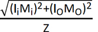
b) The allowable displacement stress range, SE, resulting from axial, bending, and torsional displacement stresses, is defined as follows:

Where,
Axial stress range due to displacement strains =

Bending stress range due to displacement strains =

Torsional stress range due to displacement strains =

Axial force range between any two conditions being evaluated
Axial stress intensification factor
Torsional stress intensification factor
Torsional moment range between any two conditions being evaluated
In-plane stress intensification factor
Out-plane stress intensification factor
In-plane bending moment range between any two conditions being evaluated
Out-plane bending moment range between any two conditions being evaluated
Allowable displacement stress range

c) The allowable limits for the sum of the stresses due to sustained loads, SL, and the stresses produced by occasional loads, SOCC are specified as follows:

(3) Allowable equipment nozzle loads and other design requirements
The allowable nozzle loads for equipment, including pumps, compressors, turbines, coolers, tanks, and vessels, are typically provided by equipment vendors. The following figures illustrate the allowable nozzle loads for a screw compressor.
| Allowable Nozzle Loads |
Nozzle Size
(NPS) |
Moments (ft-lbf) |
Load (lbf) |
| MR |
MC |
ML |
P |
VC |
VL |
| 6 |
1000 |
750 |
750 |
650 |
650 |
650 |
Other design requirements that should be met include:
-
Local stresses at support attachments (trunnions, dummies, etc.) are calculated and assessed in accordance with ASME Section VIII, Division 2.
-
Flange leakage is checked per ASME VIII, Division 2.
-
The maximum deflection of piping between supports is limited to a specified value, typically 25 mm.
-
All loads exceeding a certain value, typically 2000 lbs, on structural supports are communicated to piping design and structural engineering teams.
Piping Stress Analysis Tools
Various analysis tools are available for piping stress analysis. At CCPGE, we utilize CAESAR II and Bentley AutoPIPE for this purpose. When necessary, FEPIPE or ANSYS are also employed for detailed local stress analysis on vessel nozzles, pipe fittings, and supports.
CAESAR II and AutoPIPE are widely recognized software applications for piping stress analysis. They enable users to effectively create a piping stress analysis model and define the loading conditions imposed on the system. Based on this input, the software produces results in the form of displacements, loads, and stresses throughout the system, and compares these results against limits specified by recognized codes and standards.