Acoustical Pulsation Analysis

Reciprocating Compressors

Home Services Reciprocating Compressors
What is Acoustical Pulsation Analysis

In reciprocating compressor systems, the flow of fluid through the suction and discharge valves is intermittent, resulting in periodic pressure fluctuations which are known as acoustical pulsation. The magnitude and shape of this pulsation are influenced by the physical, geometrical, and mechanical characteristics of the compressor system. Although pulsation cannot be entirely eliminated, it can be effectively attenuated through a comprehensive acoustical pulsation analysis.

The acoustical pulsation analysis involves calculating pressure pulsations, pulsation-induced shaking forces, and pressure drops resulting from the specific attenuation measures. Typical attenuation strategies include design of pulsation suppression devices and/or orifice plates and modification of piping layouts. By performing an acoustical pulsation analysis to optimize these measures, the pressure pulsations, shaking forces, and pressure drops can be reduced to levels within the API 618 pulsation guidelines.

Acoustical Pulsations in a Reciprocating Compressor System

Why Perform Acoustical Pulsation Analysis

Performing an acoustical pulsation analysis can help identify appropriate pulsation attenuation measures and thus mitigate the risk of excessive pulsations and shaking forces in the system. Failure to address excessive pulsations and shaking forces can lead to:

Cracks on the Pulsation Bottle Resulting from Excessive Pulsations

  • Reduced compressor volumetric efficiency
  • Deterioration of valve operating conditions
  • Malfunctioning control instruments and measurement units
  • Vibrations and potential failure in the compressor and piping systems
Acoustical Pulsation Analysis Methodology
Acoustical Pulsation Analysis Procedure

Below is a flowchart outlining the procedure for acoustical pulsation analysis of reciprocating compressor packages.

  • Information collection involves gathering the necessary input data for the analysis. This includes three-dimensional general arrangement of the compressor package, compressor and cooler specification information, piping isometric drawings, vessel design drawings, gas composition, operating cases, and other relevant details.
  • Generation of model is to use analysis software to build an acoustical analysis model based on the collected input data. This includes defining pulsation systems, compressor model, bottle models, scrubber models, cooler models, piping models, and setting appropriate analysis boundary conditions.
  • The troubleshooting and verification of model is to verify the input data and perform a test run to prepare for the batch run for all specified operating cases.
  • Trial runs and developing solutions are to perform trial runs for proposed solutions. Once a suitable solution is identified where the resulting pulsations, shaking forces and pressure drops are within the API 618 pulsation guideline for all operating cases being investigated, the final solution is determined.
  • Generation of result files involves creating the analysis result files for all operating cases being investigated, and present them for selected operation cases and locations within the system.
API 618 Design Approaches

API 618 (6th Ed.) specifies two design approaches for pulsation analysis of reciprocating compressor packages: Design Approach 2 (DA2) and Design Approach 3 (DA3). These approaches are defined as follows:

  • DA2 — Acoustic Simulation and Piping Restraint Analysis.
  • DA3 — Acoustic Simulation and Piping Restraint Analysis plus Mechanical Analysis (with Forced Mechanical Response Analysis if necessary).

The table below outlines the criteria for selecting the appropriate design approach based on the cylinder power and discharge pressure of compressors.

Discharge Pressure Rated Power per Cylinder
kW/cyl < 55
(hp/cyl < 75)
55 < kW/cyl < 220
(75 < hp/cyl < 300)
220 < kW/cyl
(300 < hp/cyl)
P < 35 barg
(P < 500 psig)
DA2 DA2 DA2
35 barg < P < 70 barg
(500 psig < P < 1000 psig)
DA2 DA2 DA3
70 barg < P < 200 barg
(1000 psig < P < 3000 psig)
DA2 DA3 DA3
200 barg < P
(3000 psig < P)
DA3 DA3 DA3

The API 618 (6th Ed.) DA3 Steps details and the comparison with API 618 (4th Ed.) pulsation design study procedure are summarized as follows:

Design Approach in API 618
(6th Ed.)
Steps in API 618
(6th Ed.)
Procedure in API 618
(4th Ed.)
Content
DA2 Step 2 M2 Acoustical simulation study
M3 Performance analysis (pulsation and pressure drop effects)
M4 Mechanical natural frequency calculation and piping support design recommendation of the piping system
DA3 Step 2 M2-M4 Acoustical pulsation analysis and piping restraint analysis
Step 3a M5 Mechanical natural frequency analysis of the compressor system
Step 3b1 M6 Forced mechanical response analysis of the compressor system
Step 3b2 M7 Forced mechanical response analysis of the piping system
- M8 Dynamic and static stress calculations of pulsation suppression device internals
Optional - M9 Compressor valve dynamic response study
- M10 Low cycle fatigue analysis for pulsation suppression bottles
- M11 Piping system thermal flexibility analysis
API 618 Pulsation Guidelines

(1) Maximum allowable pulsation in piping system

Per API 618 (6th Ed.) Clause 7.11.7.3.1, the allowable pulsation limit in the piping system with absolute line pressures above 3.5 bara (50 psia) is specified as,
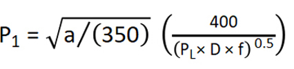
Where,

P1
=
Percentage of maximum allowable peak-to-peak pressure pulsation to the absolute line pressure (%)
PL
=
Absolute line pressure (bara)
a
=
Speed of sound for the gas (m/s)
D
=
Pipe inside diameter (mm)
f
=
Pulsation frequency (Hz)

For absolute pressures less than 3.5 bara (50 psia), the above equation shall be multiplied by

(2) Maximum allowable pulsation at compressor cylinder flange

Per API 618 (6th Ed.) Clause 7.11.7.2, the allowable pulsation limit at the compressor cylinder flange is specified as,

Where,

Pcf
=
Percentage of maximum allowable peak-to-peak pressure pulsation to the absolute line pressure at the compressor cylinder flange (%)
R
=
Stage pressure ratio

(3) Maximum allowable pressure drop

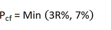
Per API 618 (6th Ed.) Clause 7.11.8.1, the steady flow pressure drop shall not exceed 0.5% of mean absolute line pressure at pressure ratios less than or equal to 1.4. At pressure ratios greater than 1.4, the value is specified as,

Where,

△P
=
Percentage of maximum allowable pressure drop to the absolute line pressure (%)
R
=
Stage pressure ratio

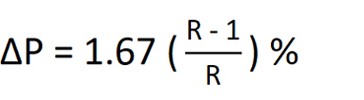
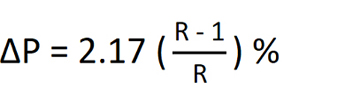
If the pulsation control device includes an integral moisture separator, the steady flow pressure drop shall not exceed 0.6% of mean absolute line pressure at pressure ratios less than or equal to 1.4. At pressure ratios greater than 1.4, the value is specified as,

(4) Maximum allowable piping acoustic shaking force

Per API 618 (6th Ed.) Clause 7.11.7.4, the allowable piping non-resonant shaking force limit is specified as,

Where,

SFp
=
Non-resonant piping shaking force guideline (N)
SFk
=
Non-resonant shaking force guideline relative to static structural stiffness (N)
SFpmax
=
Non-resonant piping shaking force guideline based on support strength (N)

The shaking force guideline is applied to non-resonant vibration. Shaking forces near resonance shall be reduced well below the guideline specified above.

In the above equation, SFk and SFpmax are specified as,

Where,

Keff
=
Effective static stiffness along the piping axis where the shaking force acts (N/mm)
V
=
Design vibration guideline given in API 618 (6th Ed.) Clause 7.11.7.4.1 (mm)
NPS
=
Nominal pipe size (mm)

(5) Maximum allowable pulsation control device acoustic shaking force

Per API 618 (5th Ed.) Clause 7.11.7.4, the allowable pulsation control device non-resonant shaking force limit is specified as,
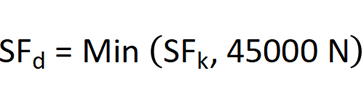
Where,

SFd
=
Non-resonant pulsation suppression device shaking force guideline (N)
SFk
=
Non-resonant shaking force guideline relative to static structural stiffness (N)

The shaking force guideline is applied to non-resonant vibration. Shaking forces near resonance shall be reduced well below the guideline specified above.

In the above equation, SFk is specified as,
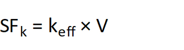
Where,

Keff
=
Effective static stiffness along the pulsation control device axis where the shaking force acts (N/mm)
V
=
Design vibration guideline given in API 618 (6th Ed.) Clause 7.11.7.4.1 (mm)
Acoustical Simulation Tools

Several analysis tools are available for acoustical simulations of reciprocating compressor packages. At CCPGE, we use Bentley PULS XM Option 3, BOSpulse, and an in-house developed program to perform the acoustical simulations in accordance with the latest API 618 Standard.

Bentley PULS XM Option 3 utilizes the transfer matrix approach to relate acoustical pressure and acoustical volume velocity across all elements of the model. It calculates pulsation-induced shaking forces along pipe segments and vessels, predicts pressure drops across each element, and compares the calculated pulsations, shaking forces, and pressure drops with the allowable limits specified by API 618 standard.

BOSpulse employs both transient (time domain) and harmonic (frequency domain) solution methods for acoustical simulations of reciprocating compressor systems. This software enables analysts to simulate periodic pressure pulsations in piping systems, compare the results against API 618 limits, and assess the impact of these pulsations on the structural behavior of the system.

At CCPGE, we have also developed an in-house pre- and post-processing program to manage the input and output data from these commercial tools across all operating cases. This program significantly accelerates the simulation process while maintaining high quality to better serve our clients' interests.

Acoustical Pulsation Analysis Example

An example of acoustical pulsation analysis for a reciprocating compressor package with the following specifications is illustrated below. The analysis was performed using Bentley PULS XM Option 3 software in accordance with API 618 Standard.

Compressor Model: Ariel KBZ/4 Power: 2796 kW
Engine: Caterpillar G3612 Speed: 800 – 1000 RPM
Number of Stages: 3 Flow Rate: 439 – 550 E3m3/D
Number of Cylinders: 4 Suction / Discharge Pressure: 0.41 MPag / 8.8 – 9.8 MPag

The calculated acoustical pulsations, represented by the maximum pulsation violation ratio, for the 1st inter-stage system of the compressor package, both before and after design modifications, are shown in the following figures. The design modifications aim to implement pulsation attenuation measures which include the design of suitable pulsation bottles with internal choke tubes and baffles, and the use of orifice plates to mitigate excessive pulsations and shaking forces.

Before Design Modifications

After Design Modifications

Comparison of Pulsation Violation Ratio

The figures below display the maximum shaking forces acting on the stage 1 discharge bottle in the system, both before and after the design modifications.

Before Design Modifications

After Design Modifications

Comparison of Selected Shaking Force

Additionally, the pressure drops and power losses resulting from the pulsation attenuation measures at the design case are detailed in the following table.

Stage No. Suction or Discharge Pressure Drop (kPa) Power Loss (kW)
Calculated API 618 Calculated API 618
1 Suction 7.71 11.26 4.53 6.62
Discharge 12.43 34.40 3.05 8.45
2 Suction 6.82 14.95 2.64 5.78
Discharge 19.26 37.41 3.66 7.10
3 Suction 20.75 36.24 3.15 5.49
Discharge 37.22 178.02 2.83 6.78
Total 104.19 312.28 19.86 40.22
Notes on Acoustical Pulsation Analysis
  • Single-Acting Operating Cases: Single-acting cases represent the worst-case scenario for acoustical pulsation analysis due to changes in the number of pulsations per cycle. Although this increases the difficulty of identifying effective pulsation attenuation measures, it is essential to include these operating cases in the acoustical pulsation analysis.
  • Multiple Compression Scenarios: Compressor packages with multiple compression scenarios, such as 1-stage and 2-stage compression, often present challenges in finding suitable pulsation attenuation measures. Each compression scenario has unique pulsation characteristics, making it difficult to develop a uniform pulsation attenuation solution that effectively addresses the needs of all scenarios.

These factors can complicate the application of standard pulsation attenuation measures, necessitating customized solutions to ensure compliance with API 618 standards.

Contact

Phone: +1 (587) 352-9788

E-mail: info@ccpge.com

Address: 801 6 Ave SW #1750, Calgary, AB
Canada T2P 3W2

Address: 801 6 Ave SW #1750, Calgary, AB
Canada T2P 3W2

Copyright © 2024 C&C PetroGas Engineering Ltd. (CCPGE) All Rights Reserved. Web Design: MornDesign